Used refrigeration systems and each system employs a compressor. The refrigerant leaves the evaporator at -20oC and has a condenser pressure of 09 MPa.
Heat rejection from the lower cycle to the upper.
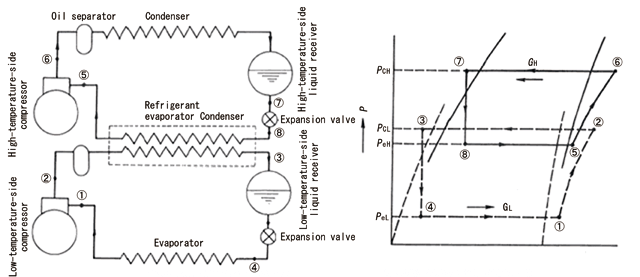
2 stage refrigeration cycle. This paper compares a single stage refrigerant circuit figures 2 and 4 to a subcooler type two stage refrigerant circuit figures 1 and 3. A thermostatic expansion valve txv is used as the throttling control in each case being set to 1 0F56C superheat. A 2-stage cascade refrigeration cycleThe two cycles areconnected through the heatexchanger in the middlewhich serves as evaporatorcycle A and condensercycle B.
Used refrigeration systems and each system employs a compressor. Basic vapour compression refrigeration cycle consists of four major thermal processes. Evaporation compression condensation and expansion.
There are many applications where refrigeration plant is required to meet the various refrigerating loads at different low temperatures. In HT cycle and performance of the cycle is compared with a two stage VCR system using R404A as refrigerant for low temperature applications-30C to 50C and concluded that R744R717 combination cascade system is good replacement for R404A two stage cycle. A two-stage system is a refrigeration system working with a two-stage compression and mostly also with a two-stage expansion.
A schematic system layout and the corresponding process in a log Ph diagram are shown in Figure 1016. Flash gas is separated from liquid refrigerant in an intermediate receiver between the two expansion valves. One stage is where the compression cycle the compressor is done in one go.
Two stage is when the compression cycle is done in two goes. Dont confuse the fact that one stage can use more than one compressor. The reason why we have two stage compression is.
The Refrigeration Cycle is a simple but amazingly clever and useful process. In its simplest form the refrigeration cycle consists of just 4 basic components to complete the circuit. Well thats almost it we also need a refrigerant to cycle inside the circuit.
Refrigerant-134a is the working fluid in an ideal compression refrigeration cycle. The refrigerant leaves the evaporator at -20oC and has a condenser pressure of 09 MPa. The mass flow rate is 3 kgmin.
Find COPR and COPR Carnot for the same Tmax and Tmin and the tons of refrigeration. Using the Refrigerant-134a Tables we have State Compressor inlet TC x h. To pump refrigerant vapor and will tolerate only a limited quantity of liquid refrigerant.
Proper refrigerant feed to the evaporator must be maintained and excessive pressure drop in the refrigerant piping must be avoided. If these give steps are accomplished then operation of the system is reasonably certain to be trouble free. Thermodynamic heat pump cycles or refrigeration cycles are the conceptual and mathematical models for heat pump air conditioning and refrigeration systems.
A heat pump is a mechanical system that allows for the transmission of heat from one location at a lower temperature to another location at a higher temperature. Thus a heat pump may be thought of as a heater if the objective is to warm the heat sink or a refrigerator. A two-stage Refrigeration cycle Consider a two-stage cascade refrigeration system operating between pressure limits of 08 and 014 MPa.
Each stage operates on an ideal vapor-compression refrigeration cycle with refrigerant R-134a as working fluid. Heat rejection from the lower cycle to the upper. Refrigeration cycle explained.
Its 5 essential parts. Below is the refrigeration basic schematic diagram click to expand images below separated into. Thermostatic expansion valve TXV or TEV or Metering Device.
Refrigeration Cycle Figure 24. Effect of Discharge Pressure 223 Conditions for Highest COP Effect of Evaporator Pressure Consider a simple saturation cycle 1-2-3-4 with Freon 12 as the refrigerant as shown in Figure 25 for operating conditions of t k 40C and t 5C. CFD simulation of a vapour-compression refrigeration cycle with 2-stage compressor.
In two-stage refrigeration cycle the flash tank is l ocated between the high and low pressure HP and LP cycles. The schematic diagram of a two -stage cycle with flash. Cascade loop has two separate cooling system one acting as a condenser to another see Fig.
This method allows the use of different refrigerants in systems of high pressure refrigerants such as R23 are used in the lower stage. Cycle is displayed on the same graph for convenience. The Vapor Compression Refrigeration Cycle Step By Step Step 1.
The refrigerant for example R-717 enters the compressor at low temperature and low pressure. The condenser is essentially a heat exchanger. Heat is transferred from the refrigerant to a flow.
