It is anticipated that small changes in the bench alignment settings. The bar map below shows 5 bars b0 thru b4 but since the angle between b2.
These members are connected by four revolute pairs forming a closed-loop kinematic chain of 1-degree-of-freedom.
4 bar linkage kinematics. This four-bar linkage kinematic analysis package plots linear velocity and acceleration curves for a specified point on the coupler link angular velocity and angular acceleration curves and coupler curves. This example shows how to solve inverse kinematics for a four-bar closed-chain linkage. Robotics System Toolbox does not directly support closed-loop mechanisms.
However the loop-closing joints can be approximated using kinematic constraints. This example shows how to setup a rigid body tree for a four-bar linkage specify the kinematic constraints and solve for a desired end-effector position. Connect joints A B1 C1 and D.
AB1C1D is the first position of the required four-bar linkage. Measure the lengths of four links according to the scale the real lengths of all links can be figured out. A1 Position Analysis of a Four-Bar Mechanism Consider the mechanism shown in Fig.
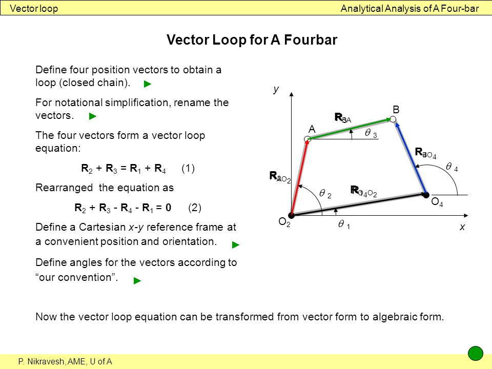
A1 in which O 2O 4 O 2A AB and O 4A are the lengths of links 1 2 3 and 4 respectively. On the other hand angles h 2 h 3 and h 4 define the angular position of links 2 3 and 4 considering the counterclockwise rotations positive. In order to determine angles h 3 and h.
Measuring absolute and relative velocities in a simple context. 4 Bar Linkage Kinematics This app lets you define the geometry and crank valocity of a four bar linkage. It outputs the velocity and acceleration of the end effector.
Uncertainties Interval Analysis Design Linkage 1. Introduction to Linkage Design The four-bar linkage is a planar mechanism consisting of four rigid members. The frame the input link the output link and the coupler link.
These members are connected by four revolute pairs forming a closed-loop kinematic chain of 1-degree-of-freedom. A point on the coupler known as the coupler point traces. 4-Bar Linkage Optimizer Posted by Ben and Wade This linkage simulator allows you to quickly check how changing the linkages bar lengths affect the path it draws as the crank is rotated.
The bar map below shows 5 bars b0 thru b4 but since the angle between b2. This Video Covers the working of a four bar linkage mechanism using a 3D animation. One should be able to form a closed triangle for a 4-bar that shows the vector equation.
VB VA VBA where VB absolute velocity of point B VA absolute velocity of point A and VBA is the velocity of point B relative to point A. At 858 the left side of the second equation containing the y terms should be -8 instead of 8. The answers for alpha_AB and alpha_BC are correctW.
This tutorial shows how to model a 4-bar linkage in Gazebo with examples using SDFormat and URDF. This is a challenge because URDF uses a tree structure to represent robot kinematics which does not permit closed loops like a 4-bar linkage. SDFormat is able to model closed kinematic loops because it uses a graph structure.
Four-bar linkage prosthetic knee mechanisms IM alignment of the prosthesis. This line is used to assemble the components of the prosthesis such that the prosthesis will provide stability in weight bearing during the first walking trials when fitted to the amputee. It is anticipated that small changes in the bench alignment settings.
ANALYSIS OF KINEMATICS AND KINETOSTATICS OF FOUR-BAR LINKAGE MECHANISM BASED ON GIVEN PROGRAM. Faculty of Mechanical Engineering University of Prishtina Hasan Prishtina Kosovo 1.