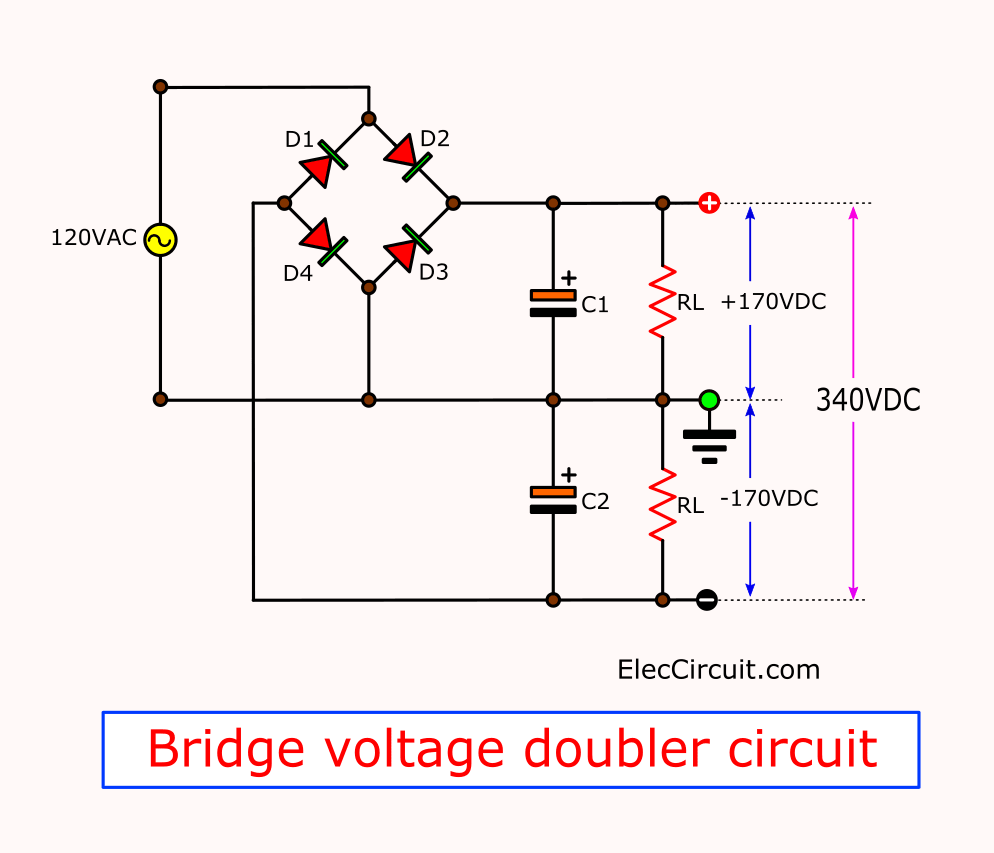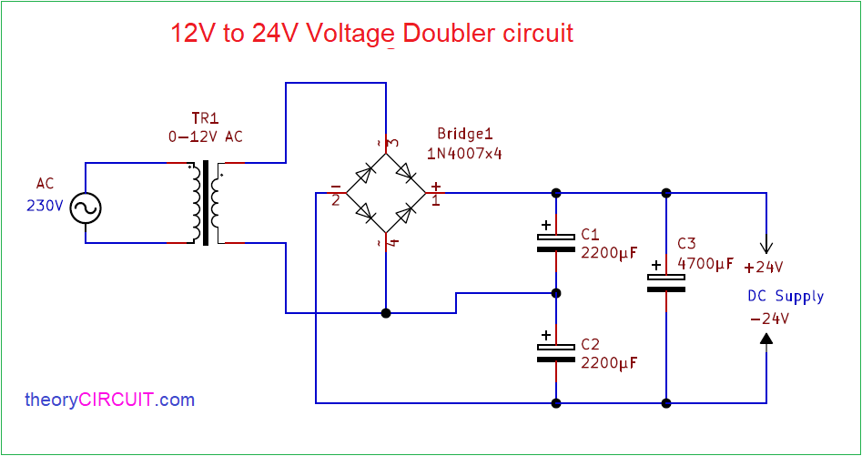
The voltage doubler is a device which delivers double the peak voltage maximum voltage. Also a center-tap dual rectifier is shown in Figure 3.

For higher-voltage output the ac power switch is turned on to realize voltage-doubler rectifier on the secondary side.
Bridge rectifier voltage doubler. By replacing two of the diodes in a bridge rectifier with capacitors we obtain the full wave voltage doubler shown on figure below. The circuit represents a pair of half wave rectifiers of opposite polarity with output taken between the two. One capacitor is charged up to the peak AC voltage on the positive half cycle and the other is charged up to the peak AC voltage on the negative half cycle.
As its name suggests a half-wave voltage doubler is a voltage multiplier circuit whose output voltage amplitude is twice that of the input voltage amplitude. A half-wave voltage doubler drives the voltage to the output during either positive or negative half cycle. The half-wave voltage doubler circuit consists of two diodes two capacitors and AC input voltage source.
The Delon bridge voltage doubler also known as the full-wave voltage doubler used in conjunction with a step-up transformer is capable of outputting voltages in the kilovolt range. In prototyping line-driven power supplies even with no transformer there is a potential shock hazard. Beware also that electrolytic capacitors will explode if polarity is reversed.
I finished my full bridge rectifierfull wave voltage doubler for my dual MOT power supply. Also i go over my plan for a mot dc tesla coil and discuss balast. The current doubler is a particularly useful rectifier configuration for low-voltage or high-current outputs.
It combines two advantagesefficient usage of the transformer secondary winding like a bridge rectifier and easy self-drive of two n-channel MOSFET synchronous rectifiers like a. To achieve wide output voltage operation full-bridge rectifier topology or voltage-doubler rectifier topology is selected on the secondary side by using an ac power switch. For higher-voltage output the ac power switch is turned on to realize voltage-doubler rectifier on the secondary side.
On the other hand ac power switch is turned off to realize full-bridge rectifier on the secondary side under lower voltage. The voltage doubler is a device which delivers double the peak voltage maximum voltage. It comprises of capacitor filter circuit which delivers double DC voltage of the peak input AC voltage.
Voltage doublers are of significant importance in devices which needs high voltage and low current. Some of the devices which fall in this category are. Half Wave Voltage Doubler.
The figure below shows the input waveform circuit diagram and output waveform. In this diagram during the positive half cycle the forward biased D1 diode conducts and diode D2 remains in switched OFF state. At this point the capacitor C1 charges upto VSmax peak 2 voltage.
In the course of the negative half cycle the D2 forward biased diode. A new phase-shifted full-bridge converter with a voltage-doubler-type rectifier for a high-efficiency power-sustaining module of a plasma display panel is proposed in this paper. The proposed converter employs a voltage-doubler rectifier without an output inductor.
Rectifier Bridges and Dual Rectifiers bridge circuit is shown in Figure 1 and a three-phase bridge for larger multiple-phase power sources is in Figure 2. Also a center-tap dual rectifier is shown in Figure 3. Note that the transformer secondary side requires twice as much winding for the same voltage across the load R L when only using two rectifiers from a dual center-tap compared to a full-wave bridge.
Typically a diode bridge having two parallel component arms is employed to rectify the fluctuating voltage. However this type of bridge is limited to handling a working voltage across the bridge in. A multiplier circuit that produces dc output voltage whose amplitude is twice the maximum amplitude of the ac input supply voltage is known as Voltage Doubler.
The circuit shows its necessity in all such applications where a high level of voltage is required when the input source is of low amplitude. Because of natural zero-voltage switching ZVS capability simple structure and high efficiency 1-5. In the rectified stage of PSFB converter full-bridge rectifier FBR center-tapped rectifier CTR and current doubler rectifier CDR can be adopted to suit for various applications.
FBR has the lowest.