Displacement diagram of a follower. Cams are either in rotary or reciprocating or oscillating motion.
It is widely used in automobile industries to direct opening and closing of inlet and exhaust valves at desire time.
Cam and follower diagram. A follower is a mechanical element with respect to which the cam rotates in an oscillating or circular motion. The follower prevents the push and pulls of the cam. The followers are used to transfer the movement to the required machine part.
The mechanism for the cams and followers depends on each other. The follower revolves in an oscillating or circular arc. Cam is a mechanical component which is a rotating circle or eclipse about the minor axis of the Follower.
Hence it can be explained easily that Cam is a mechanical component that transmits reciprocating oscillating or linear motion to Follower. Cams shape is usually an. In cylindrical cam the follower will be reciprocated or oscillates in a direction parallel to the cam axis.
The follower rides in the groove at its cylindrical surface. Check the schematic representation of the Cylindrical cam with both the reciprocating follower and the oscillating follower. Displacement diagram of a follower.
Presentation prepared by. A Cam is a rotating element which transfers its rotary motion into reciprocating motion or oscillating motion to another element known as Follower. In radial cam the follower reciprocates or oscillates in a direction perpendicular to the cam axis.
In a cam follower system the motion of the follower is very important. Its displacement can be plotted against the angular displacement θ of the cam and it is called as the displacement diagram. The displacement of the follower is plotted along the y-axis and angular displacement θ of the cam is plotted along x-axis.
From the displacement diagram velocity and. Figure 6-12 is a skeleton diagram of a disk cam with a knife-edge translating follower. We assume that the cam mechanism will be used to realize the displacement relationship between the rotation of the cam and the translation of the follower.
Figure 6-12 A Skeleton Diagram of disk cam. Cam and follower is a type of assembly both works together in any machine element. Cam and followers are the example of higher pair due to the line contact between them.
Some complicated motions are easily achieved by using cams and followers which are difficult to achieve. We can say that the cam and followers are the most important part of the mechanisms. The cams and follower.
Displacement DiagramA displacement diagram is a graph showing displacement of the follower plotted as a function of timeDegrees of cam rotation are plotted along the horizontal axis and the length of the diagram represents one revolution of thecamSince the cam speed in rpm is constant equal angular division also represent equal time incrementsDisplacement of the follower is plotted along the vertical axis. Followers Knife-edge Flat-face Roller Sperical-face Displacement diagrams Cam-follower. Usually 1-DOF system Displacement diagram types Uniform motion Constant velocity Problem.
Infinity acceleration at point where dwell portion starts Parabolic-uniform Can be shown that acceleration is constant Sinusoidal simple harmonic motion Cycloidal Cycloidal displacement diagram Graphical layout of cam profiles Terminology Trace point. Point of fictitious knife-edge follower. Today we will learn about cam terminology and its displacement diagram.
A cam is a mechanical member used to impart desired motion or displacement to a follower by direct contact. It is widely used in automobile industries to direct opening and closing of inlet and exhaust valves at desire time. Cams are either in rotary or reciprocating or oscillating motion.
The driver member in cam follower mechanism is called cam and driven member is called follower. Plate cam rotating clockwise. 20 mm diameter roller follower set 20 mm to the right of the centre line for the camshaft.
Least distance from the roller centre to the camshaft centre line 50 mm. 25 mm diameter camshaft. 0-120 follower rises 28 mm with uniform acceleration.
120-210 follower rises 21 mm with uniform retardation. The follower is pivoted at a suitable point on the frame and oscillates as the cam makes rotary motion. Classifications of followers according to line of movement.
The follower is known as a radial follower if the line of movement of the follower passes through the centre of rotation of cam. Displacement diagram for cam follower motion Cam profile Follower cam KOM - YouTube. Detailed introduction of CAM Follower httpsyoutuben6aI-bHya6sHow to Draw the displacement diagram.
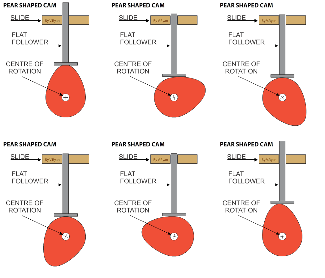
In diagram 1 the cam is in a vertical position and it slow rotates in an anticlockwise direction. As it rotates the follow drops down. In diagram 4 the follower is in its lowest position.
The cam continues to rotate and the follower begins to rise in diagrams 5 and 6 until it returns to its original position. One rotationrevolution of the cam. These are as follow.
Cam Terminology and Displacement Diagram. Base circle is the smallest circle that can be drawn tangentially to the cam profile. A trace point is a theoretical point on the follower.
Its motion describing the movement of the follower. For example a knife edge follower the trace point is at the knife edge. It is the curve drawn.
This is accomplished by keeping one or more followers in contact with the surface of a rotating cam. The follower may move as a slider reciprocating in a linear direction or as a rocker. Detailed introduction of CAM Follower httpsyoutuben6aI-bHya6sHow to Draw the displacement diagram for different follower motionhttpsyoutubefAwxgv.
