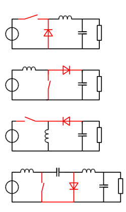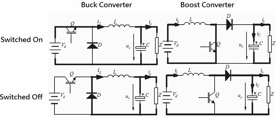
Boost converter when switch S 1 is on Figure 4. Boost converter when switch S 1 is off When switch S 1 gets turned on negative polarity gets generated across diode which makes it to get turned off.

The buck converter is a voltage step down converter and the boost converter is a voltage step up converter.
Comparison between buck converter and boost converter. Buck Converter A buck converter is known as step down converter. The figure-1 depicts circuit of buck converter. It steps down input voltage and steps up input current.
Hence Vin Vout and Iin Iout Boost Converter A boost converter is known as step up converter. In conclusion a performance comparison of a buck versus a boost converter shows the inherent superiority of the buck converter in BOM cost PCB size efficiency accuracy and EMI. On the other hand if your voltage needs a boost goodbye buck and welcome to the boost converter which becomes the only game in town.
For a battery voltage greater than 36V the buck-boost operates as a buck converter while for an input voltage less than 36V it behaves similar to a buck-boost or boost converter. Below 36V the buck-boost converter input current increases beyond the load current while the buck converter enters the 100 duty cycle dropout where the input current is limited to the load current and the output voltage tracks the input. Boost converter when switch S 1 is on Figure 4.
Boost converter when switch S 1 is off When switch S 1 gets turned on negative polarity gets generated across diode which makes it to get turned off. Now the current stress depends on the current demanded as in the buck inverter case but multiplied by lGm. This term causes that the current semiconductor stress will increased considerably if Gm is higher that is to take the advantage of boosting function of the inverterThe same occurs for the buck-boost inverter this converter has the same voltage and current semiconductor stress than the boost.
A buck converter reduces voltage and a boost converter increases voltage. Some do both and regulate the voltage to a set voltage. Some do both and regulate the voltage to a set voltage.
The main differences between the buck-boost inverter topology with traditional full-bridge buck inverter and boost inverter are summarized in Reference 83. The conventional full-bridge inverter. The buck converter is a voltage step down converter and the boost converter is a voltage step up converter.
The voltage transformation ratio depends on the the available source voltage and the. I was looking for some buck boost power management IC for my circuit i have noticed that in Texas instruments website the buck - boost is categorized into 2 category converter and controller googling them only show results for converter. I have also noticed that the buck boost controller has a higher output current rating.
251 The Buck Converter. The buck converter is a commonly used in circuits that steps down the voltage level from the input voltage according to the requirement. It has the advantages of simplicity and low cost.
Figure 1 shows a buck converter the operation of the Buck converters start with a. Cuk converter uses L-C type filter so peak-peak ripple current of inductors are less as compared to the Buck-Boost converter. 2In CuK converter when switch is closed then capacitor C provides.
Boost Converters and Buck Converters. Power Electronics - YouTube. Boost Converters and Buck Converters.
Converter is configured from buck converter but unlike buck converter it includes two inductors and two capacitors. A comparison between Zeta converter and Boost converter is done using sliding. The buck-boost just uses a simple solenoid to store the energy.
The flyback has the advantage that is uses a transformer so more freedom is available to adjudt the output voltage level turn ratio but a transformer is more complex and more expensive than a single solenoid. From switch-stress point of view they are the same. CMCOT converters can achieve 20 30 better load transient behavior when compared to standard current mode buck converters.
CMCOT also is less sensitive to noise in low duty-cycle applications. Due to its very small minimum ON time the CMCOT buck can be used for applications with larger step-down ratios. CMCOT converter switching frequency will show some deviation during load transients.
2 Inverting Buck-Boost Converter The diagrams in Figure 1 show a comparison between an ordinary buck DCDC converter and the IBB. The buck converter takes a positive input voltage and converts it to a positive output voltage of smaller magnitude. The IBB takes a positive input voltage and coverts it to a negative output voltage with a.