Damage Layers in Si vs. Higher resolution imaging.

The operation of the FIB instrument is discussed and the conventional and lift-out techniques for TEM specimen preparation and the advantages and disadvantages of each technique are detailed.
Ion milling vs fib. Focused Ion Beam FIB Similar to SEM Energized Ga ions Applications Sputtering Ion Milling Imaging Circuit Edit Figure. Focused Ion Beam FIB Milling The Focused Ion Beam FIB technique is analogous to Scanning Electron Microscopy SEM in that it scans a focused probe beam in this case ions rather than electrons across the surface of interest. This beam can be used to generate high-resolution.
Ion milling with noble gas ions can be seen as physical ion beam etching. Milling with reactive ions is a chemical etching technique. To gain time ion milling is often done with beams of higher energy andor with higher current densities compared to sputter cleaning.
Typically a distinction is made between focused ion beam FIB milling and broad ion beam BIB milling. The majority of FIB milling is done with highly focused and high energy gallium ions often 30kV. The use of focused ion beam FIB milling for the preparation of transmission electron microscopy TEM specimens is described.
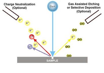
The operation of the FIB instrument is discussed and the conventional and lift-out techniques for TEM specimen preparation and the advantages and disadvantages of each technique are detailed. The FIB instrument may be used for rapid site-specific preparation of both. A focused ion beam FIB instrument is almost identical to a SEM but uses a beam of ions rather than electrons.
The focused ion beam can directly modify or mill the specimen surface via the sputtering process and this milling can be controlled with nanometer precision. By carefully controlling the energy and intensity of the ion beam it is possible to perform very precise nano-machining to produce minute. FIB milling of-fers a host of capabilities beyond those exhibited by traditional Ar ion milling including.
1 sample extraction from extremely small volumes of unpolished material. 2 site specificity at the submicrometer scale. 3 sample imaging by either second-ary ions or electrons during the milling procedure.
Focused Ion Beam FIB technology has been the pre-eminent tool for microcircuit editing for almost a decade and became the preferred microscopy sample preparation tool for site-specific applications. The FIB can both create and modify microstructures. This is accomplished by using the FIBs precision capabilities to 1.
오늘은 sample을 TEM으로 보기 위해서 할 수 있는 공정 두가지를 설명해드리려고 합니다. 1 Focused ion beam FIB 가 있고 2 Ion milling 일종의 atomic layer etching이 있습니다. 먼저 TEM을 간단히 설명드리겠습니다.
TEM transmission electron microscope은 주로 sample의 단면을 보기 위한 현미경입니다. 위에서 아래로 전자빔을 쏴서 전자를 샘플로 투과시킵니다. 샘플속의 구조 물질의.
Focused-ion-beam FIB systems have been used for several years in fail-ure analysis of integrated circuits and the repair of photomasks. For integrated-circuit failure analysis the FIB is used for the selective removal of materials known as milling in areas of the circuit so that the circuit cross sections can be examined. The problem with milling through an inte-.
Application space for ICP ion source. FIB Large area FIB cross-sectioning. Micromachining custom apertures machining steps for micro-mechanical devices Low Energy amorphous layer removal SIMS Faster low energy depth profiling.
Higher resolution imaging. Ion milling process allows to eliminate atomic layers from a sample. In order to know the milling rate in the same way as sputtering one can fix the power and thus more or less expect a.
The IM4000Plus Series Ion-Milling Systems are the second-generation of IM4000 series hybrid instruments that support Cross-Section Milling and Flatmilling. A wide variety of system configurations are available. Standard Cooling Air Protection and Cooling Air Protection.
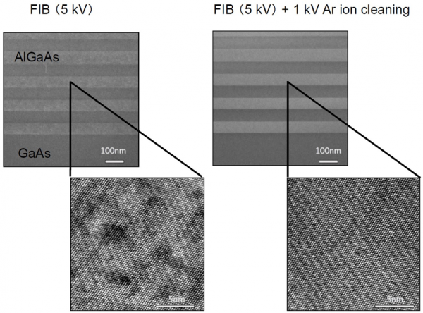
Faster milling with improved ion optics 500 μmh at 6 kV. High energy focused ion beam FIB milling produces ion-induced damage into TEM samples and a certain amount of Ga ions implantation cannot be avoided. Additional polishing of FIB lamellae at low voltages can damage the sample further.
To overcome these disadvantages a low-energy Ar -milling of a FIB. FIB works in a similar way to scanning electron microscopy SEM but instead of scanning electrons over a surface an ion beam is used. As the focussed ion beam is more energetic than an electron beam it can directly alter or mill the surface of a sample via a sputtering process which can be precisely controlled at a nanometre accuracy.
This allows the ion beam to be used for detailed nano. Damage Layers in Si vs. Ion Dose during 30 keV FIB Milling S.
Rubanov Electron Microscope Unit Bio21 Institute University of Melbourne Victoria 3010 Australia Focused ion beam FIB systems have been widely used over the last two decades for cross-sectional and plan-view TEM specimen preparation. However an inevitable result of the FIB. The high-energy Ga ion beams used in focused ion beam systems form defected amorphous andor implanted layer in the specimen.
FIB in general produces TEM samples which are less suitable for high performance analytical STEM HRTEM HRSTEM high spatial resolution EELS and. This study explores the usage of a neon focused ion beam Ne FIB as an alternative to the traditional gallium focused ion beam Ga FIB for the task of milling into the III-V compound semiconductor material GaAs. While the Ga FIB is more commonly available it is known to produce undesired artifacts such as the formation of gallium rich droplets distributed randomly on the milled surfaces.
We reproduce this effect and compare directly with the Ne FIB.