Zinggy University of Toronto Institute for Aerospace Studies 4925 Du erin Street Toronto Ontario Canada M3H 5T6 A two-dimensional Newton-Krylov aerodynamic shape optimization algorithm has been modi ed to incorporate the prediction of laminar-turbulent transition. The aim was to increase LD of general aviation aircraft business jets and sport aviation.
NASALangleyViken NLF 1-0414F natural laminar flow airfoil.
Natural laminar flow airfoil. For the present effort a new approach called a slotted natural-laminar-flow SNLF airfoil Ref. The SNLF airfoil concept is similar in nature to the slotted supercritical airfoil concept Ref. 6 in that it employs a slot to allow a pressure recovery that would not be possible for a.
Airfoils Inc State College Pennsylvania 16803 A natural-laminar-flow airfoil the NLFI-01l5 has been recently designed for general-aviation aircraft at the NASA Langley Research Center. During the design of this airfoil special emphasis was placed on experiences and observations gleaned from other successful general-aviation airfoils. For example the flight lift-coefficient.
These requirements are considered in the design of a natural laminar flow airfoil section for winglet applications and chord Reynolds number of 1 to 4 million. Winglet airfoil section characteristics which significantly influence cruise performance and handling qualities of an airplane are discussed. Slotted natural-laminar-flow SNLF airfoils are a novel aerodynamic concept that enable significant performance improvements over conventional single-element NLF airfoils.
The S207 SNLF airfoil has been designed using requirements derived from a transonic truss-braced wing commercial aircraft configuration. NASALangleyViken NLF 1-0414F natural laminar flow airfoil. Max thickness 142 at 466 chord.
Max camber 24 at 537 chord. Source UIUC Airfoil Coordinates Database. The dat file is in Lednicer format.
NASALangleySomers-Selig-Maughmer NLF 1-0115 natural laminar flow airfoil. Max thickness 15 at 441 chord. Max camber 18 at 30 chord.
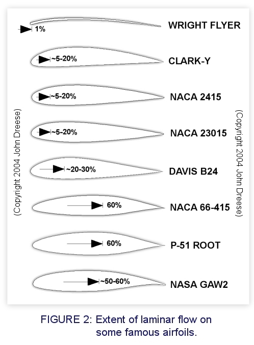
Source UIUC Airfoil Coordinates Database. Natural-laminar- ow NLF airfoil is considered to be one of the key technologies to reduce drag and thus improves performance signi cantly. ManyNLFairfoilshavebeendevelopedinthepastForexample in the early 1940s NACAdeveloped the 6-series airfoils1thathave appeal because of their low drag.
For the 6-series airfoils however. An airfoil designed for minimum drag. And uninterrupted flow of the boundary layer is called a laminar airfoil.
The Laminar flow theory dealt with the development of a symmetrical airfoil section which had the same curvature on both the upper and lower surface. Improve aerodynamic efficiency NASA developed the Natural Laminar Flow NLF airfoil series in 1970s based on computer optimization techniques1. The aim was to increase LD of general aviation aircraft business jets and sport aviation.
Profiles were optimized to maintain laminar flow up to XC 05c while making sure that premature. Design of a Slotted Natural-Laminar-Flow Airfoil for a Transport Aircraft A 1349-percent-thick slotted natural-laminar-flow airfoil the S207 for a transport aircraft has been designed and analyzed theoretically. The two primary objectives of high maximum lift insensitive to roughness and low profile drag have been achieved.
The drag-divergence Mach number is predicted to be greater than 070. The natural laminar flow airfoil shape design at transonic regime is solved using multi-objective evolutionary algorithms in this paper. A shock wave control bump is used to reduce wave drag of natural laminar flow airfoil in transonic flow and the eN transition prediction method based on the linear stability theory is used to predict.
Natural-Laminar-Flow Airfoil and Wing Design by Adjoint Method and Automatic Transition Prediction Jen-Der Lee and Antony Jamesony Stanford University Stanford California 94305 USA. This paper describes the application of optimization technique based on control theory. Of Natural Laminar Flow Airfoils Bradford E.
Green Joint Institute for Advancement of Flight Sciences The George Washington University Abstract A design method has been developed by which an airfoil with a substantial amount of natural laminar flow can be designed while maintaining other aerodynamic and geo-metric constraints. After obtaining the initial airfoils pressure distribution at the. An airfoil or aerofoil is the cross-sectional shape of a wing.
Blade of a propeller rotor or turbine. Or sail as seen in cross-section. A solid body moving through a fluid produces an aerodynamic force.
The component of this force perpendicular to the relative freestream velocity is called lift. The component parallel to the relative freestream velocity is called drag. An airfoil is a streamlined shape that is.
Optimized Natural-Laminar-Flow Airfoils J. Zinggy University of Toronto Institute for Aerospace Studies 4925 Du erin Street Toronto Ontario Canada M3H 5T6 A two-dimensional Newton-Krylov aerodynamic shape optimization algorithm has been modi ed to incorporate the prediction of laminar-turbulent transition. 1992 Subsonic Natural-Laminar-Flow Airfoils.
Barnwell RW Hussaini MY. Eds Natural Laminar Flow and Laminar Flow Control. Springer New York NY.
Publisher Name Springer New York NY. Supercritical natural laminar flow airfoil optimization for regional aircraft wing design Aerospace Science and Technology Vol. 43 An improved orthogonal grid generation method for solving flows past highly cambered aerofoils with and without roughness elements.
These above new optimized natural-laminar-flow NLF airfoils presented the outstanding performance in different aspects for low-speed flight at LRN but they can scarcely be implemented in the propeller tip.
