Kgkilogram mmeter NNewton ssecond the calculator allows a variety of units. 4 reviews 3295 downloads 21976 views.

Kp Correction factor for relieving capacity vs.
Thermal relief valve sizing equation. These standards outline several equations for sizing relief valves for various flow conditions such as liquid flow gas flow critical and sub-critical steam flow and two-phase flow. Before we consider the subject of relief valve sizing any further we should firstly understand some of the terminology used. Hi There So far Ive not seen anybody doing calculations for Thermal relief valves when there is a requirement for a TSV usually a valve of minimum size 34 x 1 OR 12 x 34 available is picked up.
This size of the valve is usually 10 to 50 times more than what it is required. Calculation of Thermal Relief Rate. The volume change of a liquid for a given temperature changes is calculated as follows.
V Δ C e T 1 T 0 V 0. Displaystyle V_ Delta C_ e times left T_1 - T_0 right times V_0 V Δ. For liquid service the sizing calculation is based on the fundamental equation for liquid discharge through an orifice 2.
1 where u is the average discharge velocity of the fluid through the relief orifice in units of distancetime. Types of orifices or valve bodies a basic liquid sizing equation can be written as follows Q C V P G 1 where. Q Capacity in gallons per minute C v Valve sizing coefficient determined experimentally for each style and size of valve using water at standard conditions as the.
Kp Correction factor for relieving capacity vs. Lift for relief valves in liquid service see Equations 1 2 K sh Correction factor due to the degree of superheat in steam K sh 10 for saturated steam. Set the Relief Pressure.
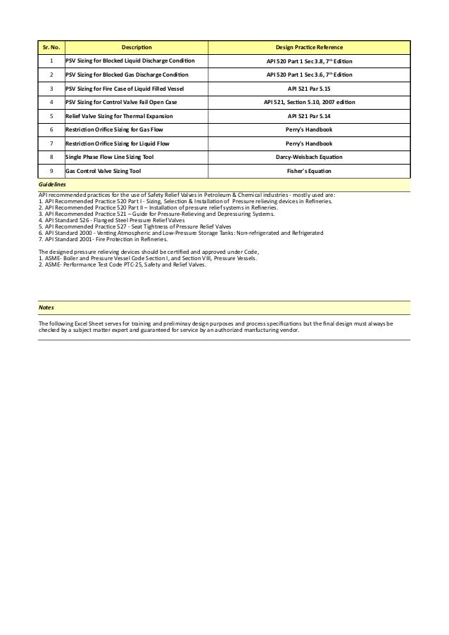
The Relief Pressure is generally determined by the equipment being protected and is calculated as Relief Pressure Set Pressure Overpressure. By default ProMax uses the stream pressure as the Set Pressure and a 10 Over Pressure but these can be modified for your analysis. As far as sizing goes there is an equation in API for thermal expansion.
Also there is a more accurate method in Perrys. If your system is ASME code stamped then you need to have an ASME rated relief device. By knowing the required set pressure and discharge capacity it is possible to select a suitable nominal size.
In this example the set pressure is 4 bar g and the fault flow is 953 kgh. A DN3250 safety valve is required with a capacity of 1 284 kgh. Yarway ARC Flow Control Valve Sizing Tank Vent Sizing for Pressure Relief Valve API 200ISO 28300 or Free Vent API 2000 ISO 28300 6th edition Sizing Reaction Force Calculations.
Variables for Liquid Relief Valve Sizing and Flow Back to calculation Units shown in SI for use in equations. Kgkilogram mmeter NNewton ssecond the calculator allows a variety of units. A Effective discharge area m 2.
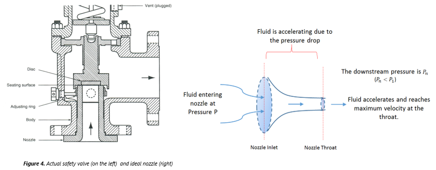
Flow area constricted in the valve the geometry resembles a nozzle and area is determined by applying the equation for flow in an isentropic nozzle56 The required orifice area for a relief valve is. 𝐴 𝐾𝐷𝐺 1 where 𝐴 is the area of the valve is the mass flow rate through the valve 𝐺 is the mass flux and K D. Note that the relief pressure can not be set higher than the maximum rated working pressure of any equipment in the system.
If the operating pressure is right below the relief pressure of the valve the valve may start leaking. A rule of thumb is to set the relief pressure 10 above the working pressure of. The following formula is used for sizing valves for steam service at 10 overpressure.
This formula is based on the empirical Napier formula for steam flow. Correction factors are included to account for the effects of superheat back pressure and subcritical flow. An additional correction factor K.
Control valve sizing procedures are based on accepted mathematical methods such as those detailed in ISA-750101-2007 Flow Equations for Sizing Control Valves. These methods can be used to develop accurate valve sizes however during the course of plant design control valves are often sized based on a future maximum design process load. Never base relief valve sizing for gas-filled vessels on API 521 equationsexcept maybe for early phase studies for cost estimation purposes.
For detailed design and actual installation purposes always base relief valve sizing on dynamic simulations with rigorous modelling of the heat transfer process in order to avoid grossly oversized PRVs. Blocked Liquid Discharge Case Consider a vessel relieving hydrocarbon at 300000 kgh which has a relief valve pressure set at 18 barg. Considering a non-fire case the over pressure is taken to be 10.
For preliminary sizing the back pressure at the relief valve discharge is considered to vary between 0 barg to 4 barg. This excel workbook provides simplified empirical equations based o. 10 reviews 5346 downloads 29801 views Added 11 May 2015.
Valve sizing single and 3 more. MS Excel workbook macro enabled for the sizing of single and two. 4 reviews 3295 downloads 21976 views.
Satpute thermal relief load pressure and 1 more. For systems where liquid product may be trapped in a pipe section of an extended period of time thermal expansion can become a problem. Heating of the fluid in the pipe results in a rapid pressure rise as the fluid expands which can quickly exceed the design pressure of the pipeline.
The damaging effects of the thermal expansion can be mitigated through the use of thermal relief valves and.