You can refer to the image earlier in this post where the formulation of the equation to calculate Aspect Ratio. Classification of wing walls.

52 shows the landing procedure.
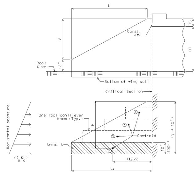
Wing wall length calculation. Wall Thickness t 100 ft. Live Load Surcharge Height S 200 ft. BDM 11362 End Height h 300 ft.
Wingwall Length L 2000 ft. Abutment Width A 300 ft. Skew Angle θ 3000 degrees Backfill Unit Weight γ1 0130 kcf CDOT Class 1 Angle of Internal Friction of Backfill Φ1 340 degrees.
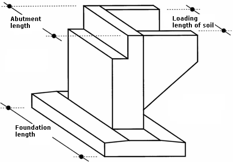
Geometry for splayed wing walls. Plan on Wing Wall. X slope to road under bridge.
Y slope from road over bridge. L length of sloping wall. K length of horizontal wall.
V verge width to end of wall. Z 1 level at bottom of embankment. Z 2 level at back of verge on road over bridge.
Wing area A is the sum of the plan view areas also known as cross-sectional areas of both wings and some component resulting from the area of the fuselage or body of the plane. Velocity and wing area can be easily calculated. Air density needs to be measured and tables of typical values have been constructed since before powered flight first began.
The area of the inner taper in the fuselage. The exact size of the wing area is not really import ant. All that is needed for the calculations is a standard reference wing area Sref.
Lets take a look at the calculation for lift in cruise flight for example. Mg L 1 2 v CL Sref ρ 2. The conception of a bridge wing wall of minimum length and of minimum area was given to the author by Mr.
Ward BSc AMICE AMIMunE Chief Assistant Engineer to the Salop County Council. This gentleman made a tour of parts of West Germany in 1957 for the purpose of studying post-war bridge and road design and noted the practice of German engineers of using triangular wing walls lying in the plane of the bridge parapets. Classification of wing walls.
Wing walls can be classified according to their position in plan with respect to banks and abutments. The classification is as follows. Used for small bridges on drains with low banks and for railway bridges in cities weep holes are provided.
Used for bridges across rivers. They provide smooth entry and exit to the water. The splay is usually.
For stability overturning sliding and bearing of culvert wingwalls and such where the length less than 4 times the height we use the height at 13 the length from the high end ie. For a wall that tapers from 12 high to 6 high wed size the footing for a 10 retained soil height. Rod Smith PE The artist formerly known as HotRod10.
Between the wings and body. The parallel-to-abutment-centerline wings or elephant-ear wings as shown on the Standard Details for Wings Parallel to A1 Abutment Centerline should be used for grade separations when possible. This wing type is preferred because it increases flexibility in the abutment it.
Quantities for two wings multiply the tabulated values for two wings one structure end. To determine total Quantities shown are based on an average wing height 0 Culvert Skew N Number of Culvert Spans Ltw Culvert Toewall Length Lw Length of Long Wingwall A Length of Short Wingwall SL1 Side Slope Ratio Horizontal1 Vertical. Then the calculation should be made for wing walls as follow -PCC Length x Breadth x Depth x Nos PCC 6 x 4 x 2 x 2 96 cft Therefore total PCC under the ground level 208 96 304 cft.
To learn the calculation process for the brickwork over and under the ground level go. The box culvert length calculator is a tool developed for the fast and easy checking of culvert barrel length and structural class of culvert. The calculator takes into account the roadway cross section skew vertical profile and culvert properties to arrive at the barrel length required and the approximate maximum and minimum fill height over the culvert and in turn the structural class.
Calculating the Wing Area for Constant Chord Tapered and Delta Wings. In order to determine the wing loading you must know the wing area. Wing area for model aircraft is always given in square inches in 2 with the exception of European kits that give area in metric units such as square centimeters or square decimeters.
Why Wing Area is Important. Taken on its own wing area is not. Lenth 1A Wing Lenght x Sin Same for other wings Lenth 1B Wing Length x Sin Wing 1 Angle Same for other wings Slopes 1B 2B 3B 4B are usually assumed to be 21.
Sheeting starts form Internal Corner. 1 stud width in from end Internal Sheet. Wall Framing Calculator - Stud Spacing and Sheeting Fit.
Running measurements are and on - From start of wall to near side of each stud. Make the mark then put an X on the far side to denote stud placement. The landing field length is calculated according to CSFAR from the landing distance sL and a safety factor.
This safety factor is 106 1667 for jets and 107 1429 for turboprops. 52 shows the landing procedure. Loftin 1980 contains a statistic that gives.
Each storey of each. For the common wall add the demand calculated for each building. For a chimney relying on the building for support refer to Clause 5345.
For a wing projecting more than 6m see Clause 515 treat as a separate building with sheets A B for each. For the common wall add the demand calculated for each building. Apron Wall - Also known as a cutoff wall.
A vertical non-structural concrete wall built across the full width of the ends of box culverts and extending below the level of the bottom slab. Bar Mass - The mass of a reinforcing bar per unit length kgm. Bearing Capacity - The maximum load that can be applied to a soil at the respective limit state.
Aspect ratio is a measure of the ratio between the span of the wing to its chord. In most cases the wing chord is not equal along the length of the span untapered which is why aspect ratio is most commonly calculated by dividing the square of the wing span by the reference wing area. You can refer to the image earlier in this post where the formulation of the equation to calculate Aspect Ratio.